


Corner window in the ArCADia-ARCHITECTURE program
Here are some ways to get around the lack of a corner (bay) window option.
1.
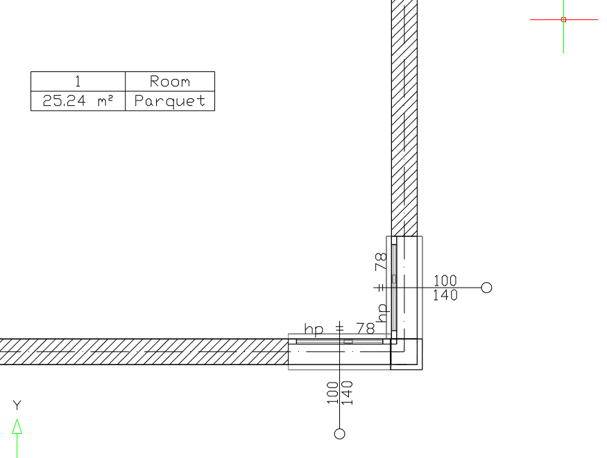
Draw the walls of the corner in which you want to place the window to their inner edges. Next, we shorten one of the walls by about 0.5 cm. In order to do that, select the wall, choose option  Extend/trim wall from the edit window and mark the end of the wall that is to be trimmed. If you are working in ArCADia, maximally enlarge the room corner view and trim the wall, ending it as close as possible to the other one, but so that the edges do not touch.
You indicate the inner corner, or wall connection, move the mouse along the wall to be shortened (moving the cursor away from the corner), type 0.5 and confirm with Enter. The wall has been shortened. Now, to close the room, connect the corners of the walls with a virtual wall.
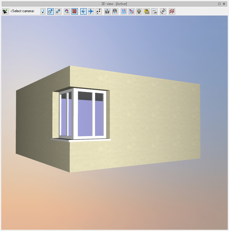
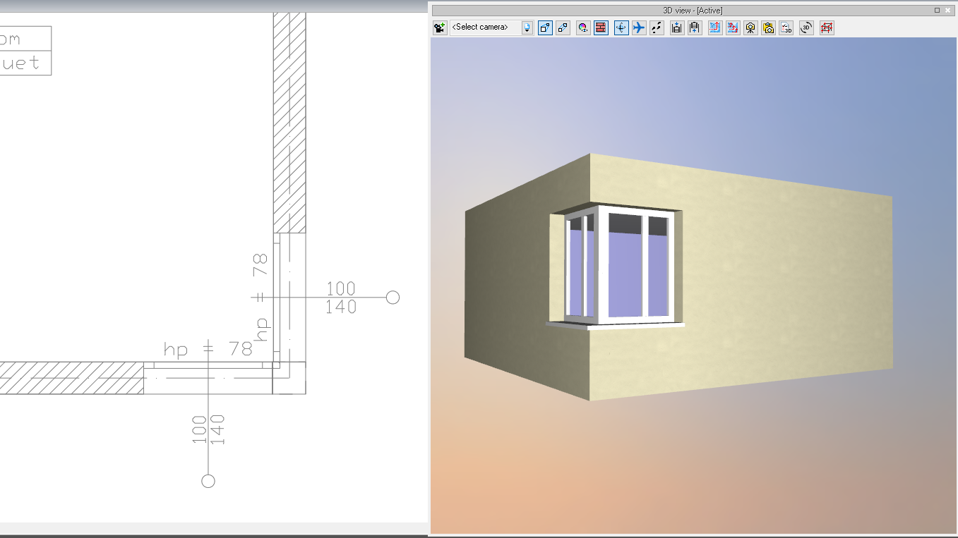
Insert the windows at the inner edge of the wall so that they touch each other.
Insert 2 columns in the corner, from the level zero to the height of the windowsill and from the end of the window to the top of the level.
Finally, the only thing left is to insert a column at the joining of the windows and mask the sill by inserting either a column or a solid in its place.
2.
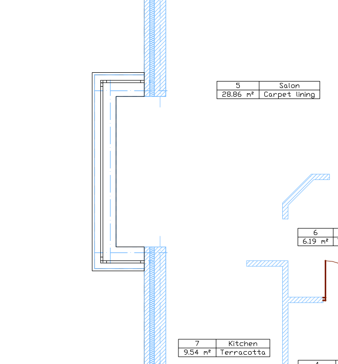
Draw the floor plan. Insert virtual walls in the place where the corner window is to be located on the inside of the walls.
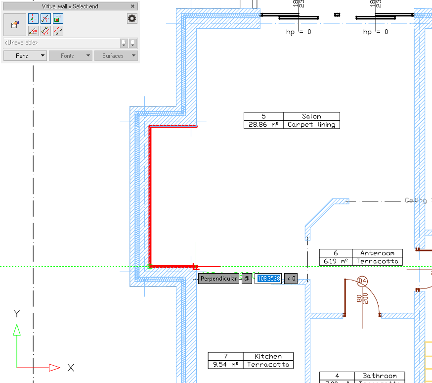
Then, mark the walls in which the windows are to be introduced and define their height to the windowsill in their properties, e.g. 80 cm. It is best to enter these walls in one group.
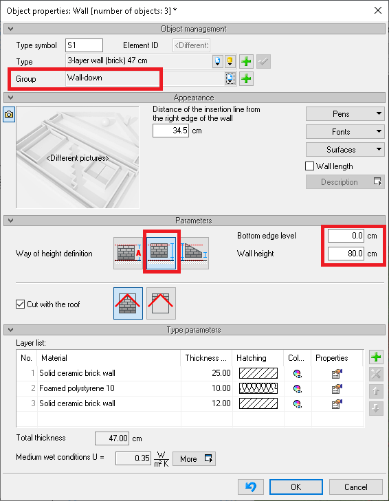
You then introduce new walls from the height of the end of the window to the end of the level and enter them into the independent group as well.
In the described case, in the bay window, you still need to insert walls at the height of windows, which should also be in a separate group. Remember that the heights of the walls should be well aligned and not overlap.
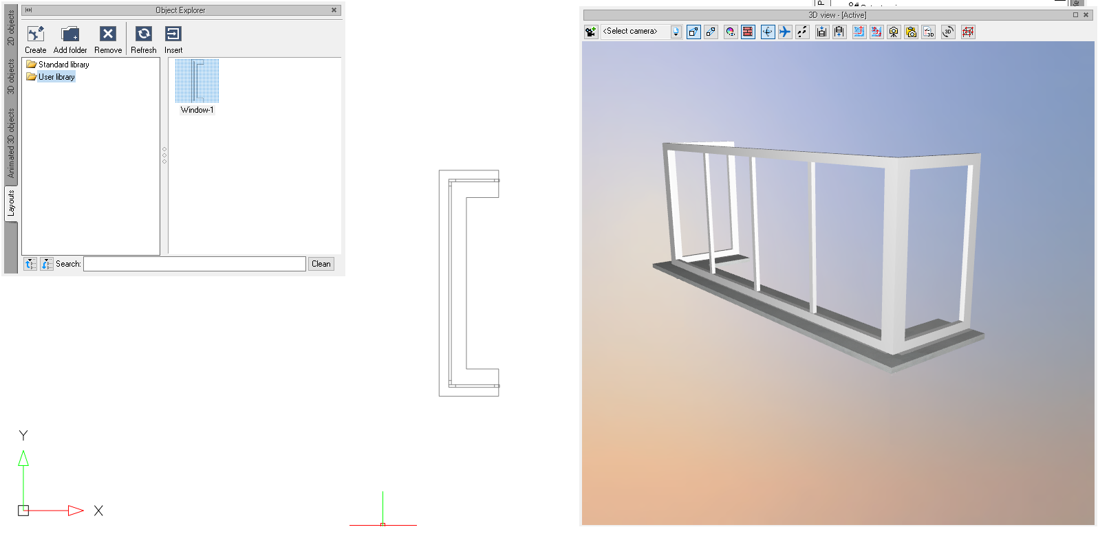
You insert a window, creating it from a solid. You start from the windowsill, which you insert at the height of 80cm using the


Now we suggest using lines to mark the place where the window is to be inserted, which will facilitate further work
After sketching, construct the window, starting with the window frame, e.g., its bottom part. Draw (with any edge) a solid along the auxiliary lines with the


The only thing left to do is to introduce the glass, which we will also make from a solid, giving it a width of 3 cm (glass, compartment, glass) and the material for all surfaces - window glass. The height of the glass should be from the lower to the upper frame, although it will not be a problem if it goes into these frames. Finally, we can enter the window division in the same way (remembering to change the material from the glass to another one) and save it to the layouts for re-use.
3.
Another way is to split the corner walls where you want the windows to end. Then, the walls in which the windows are to be introduced are narrowed to the width of the window frame.

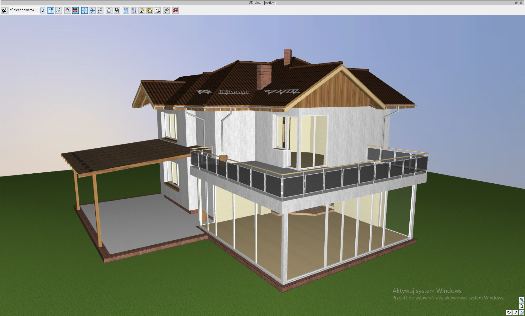
Enter the windows, and then with the Solid option, fill in the bottom and top parts of the wall so that they look to have the same thickness. Here, please look at the screenshot above, where there are clearances at the edges of the walls - also there it would be a good idea to insert a solid, which, by assigning it to a separate group, you can exclude from the View.

Copyright © 2021 ArCADiasoft
ГОЛОВНА | ПРОДУКЦІЯ | ПРО НАС | КОНТАКТИ | ДЛЯ ПРЕДСТАВНИКІВ