


Ventilation of rooms and modeling of the installation routes
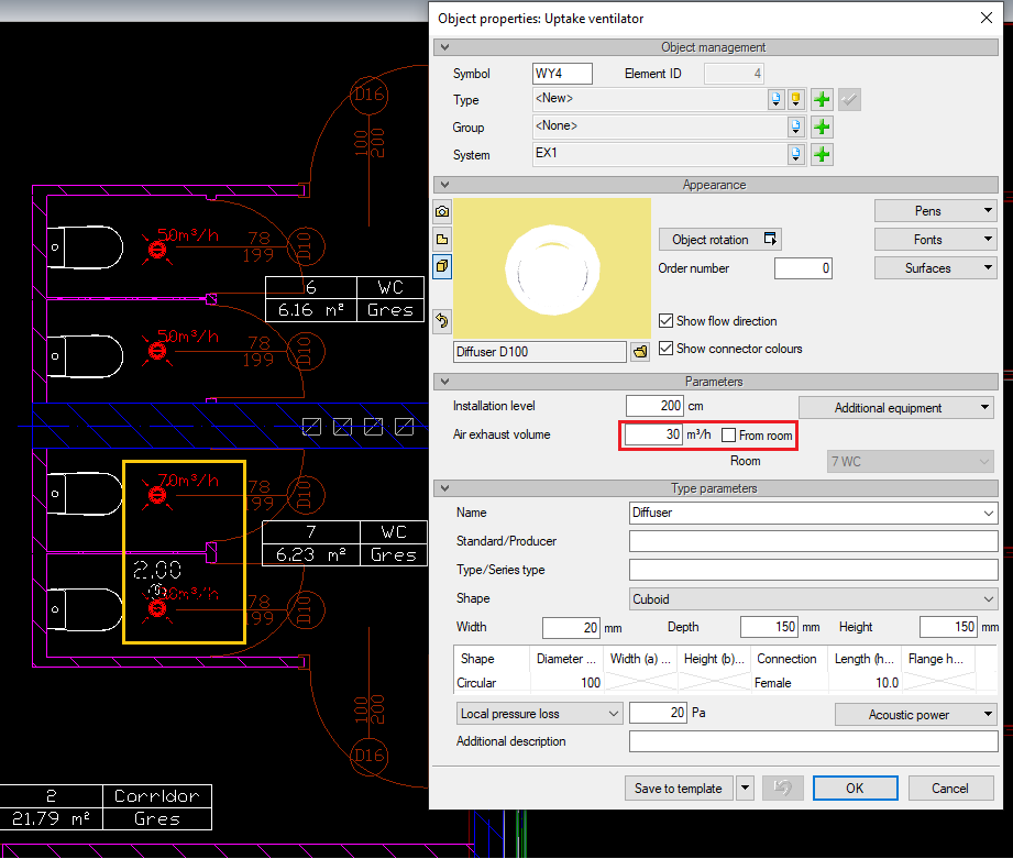
Fresh air is supplied to rooms and used air is removed by means of the final elements of the installation - air intake and outtake. If such an object is placed within a room, the amount of ventilation air (rounded to 5 m3/h) will be automatically assigned to it, resulting from the testing and calculations for this room.
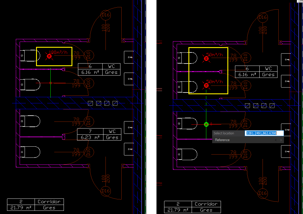
In traditional design, architectural changes that involve changes to the ventilation air balance force the designer to rewrite efficiencies already assumed once - this often results in accidental errors and the resulting frustration of an unintended, unbalanced calculations and wasted valuable time looking for the error. If the design was done in accordance with ArCADia BIM, when the calculation change, the values are updated to the new, correct values. Similarly, if the number of intakes and outtakes in a room is changed - the program divides the amount of ventilation air proportionally between the elements and adjusts it to the new design. Of course, the user can also enter their own values for the designed ventilation air volume.
In the next step, you should plan the concept of the air distribution for the building, find suitable places for the installation of devices and the location of the air intake and outlets in accordance with the regulations. In this aspect, no computer program can replace the knowledge and experience of the designer, but the created 3D model can facilitate the work and avoid mistakes at this stage. The 3D view will clearly show any binding joist or troublesome height faults, not always precisely described in the initial stage of work on the project. After creating the concept, all that remains is the drawing part, where you can count on the help of computer programs.
Drawing a network of ducts in ArCADia BIM is intuitive and comparable to drawing polylines in CAD programs. The user selects the dimensions of the duct from round, rectangular and oval ducts and then points on the view of the successive points of the installation route. Bends, elbows, tees and four-way pieces are generated automatically, the installation can be moved without disconnecting or changing the height of a group of elements.
Please check our quick tutorial on YouTube:
https://www.youtube.com/watch?v=_nehCvZn8Qk&t=61s

Additionally, in the duct insertion window, after entering the air flow value, the designer has a preview of the flow velocity in the selected channel and the possibility of introducing corrections of the channel size on the go. This is important as often, the later need to change the size of the duct may force a change of the route of the already drawn installation (e.g. a wider duct will no longer fit in the corridor or between the binding joists).

Ventilation fittings can be defined from any of the available objects (or add your own) and connected to the installation in a chosen place. The inserted object is freely rotated by the user in 3D space. When routing the ducts, you can insert appropriate control fittings, additional devices for air processing, damping elements, etc.
Drawing installation with a 3D view and the actual shape and size of the elements can help avoid serious errors that would be difficult to correct at a later stage. In the properties of ventilation ducts there is a possibility to use thermal insulation. The user himself defines the thickness and material of which it is to be made.

In the 2D drawing and 3D view the duct will be thickened by the set value. By designing the installation in the BIM model, the user has an accurate picture of the distance between insulated duct and walls or other installations. The figure below shows a duct without insulation and an insulated duct in collision with a column.

Copyright © 2021 ArCADiasoft
ГОЛОВНА | ПРОДУКЦІЯ | ПРО НАС | КОНТАКТИ | ДЛЯ ПРЕДСТАВНИКІВ