A New View in ArCADia 12
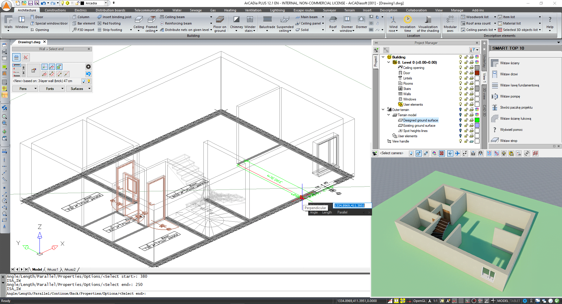
When drawing your first project in ArCADia 12, you can see additional lines that have not existed up to now. Even if you have already worked with ArCADia 12, because you were finishing off a project…. Now there is something different. It is especially visible when inserting doors, windows or the terrain. Suddenly you have door handles and extra lines running through the drawing. And more surprisingly, you can't turn them off ...
Are you sure?
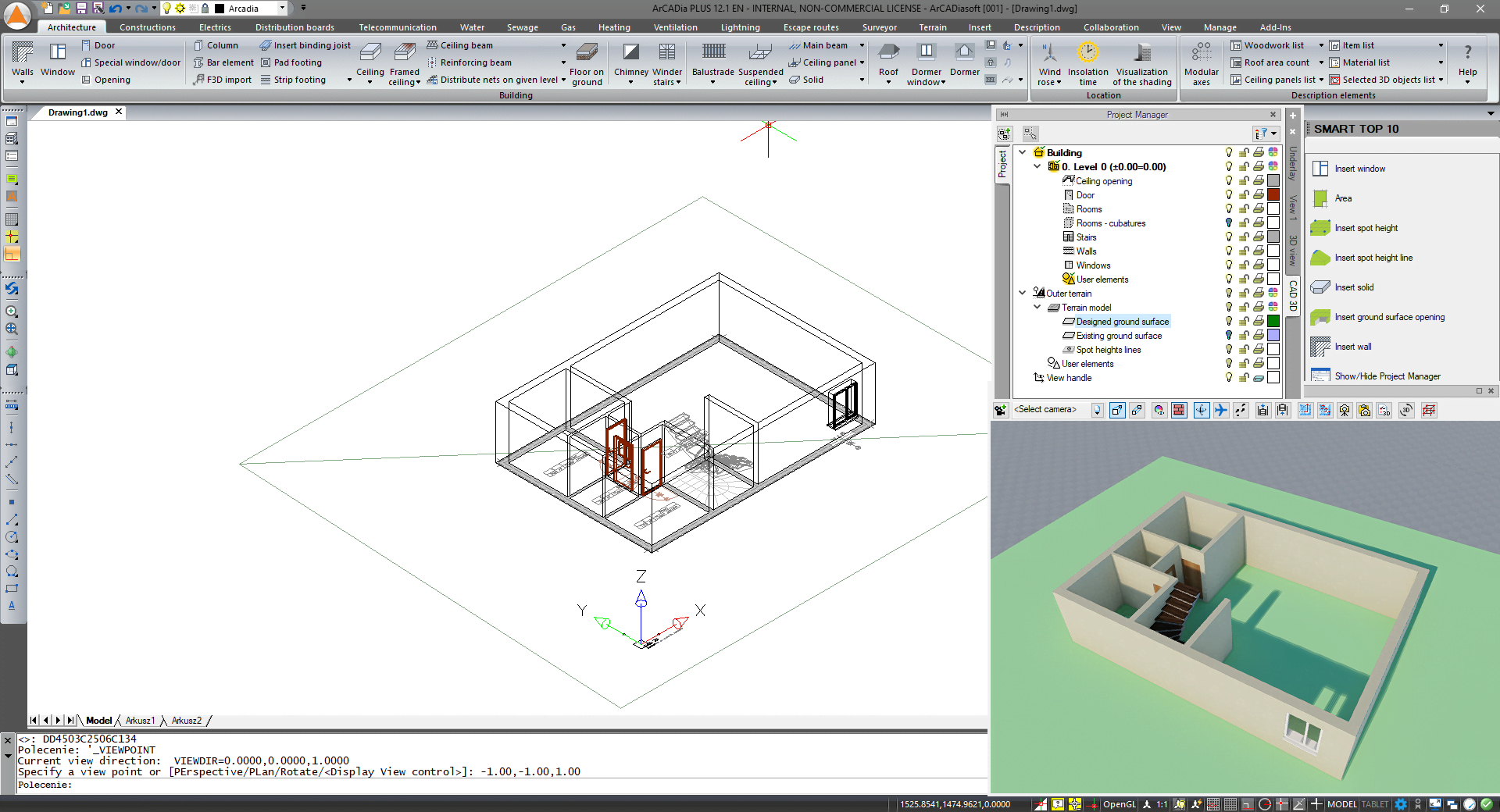
In the screenshot above, you can see in the Project Manager window that in View 1, the terrain is turned off, and a green line passes through the drawing, as if from the terrain ... although inserted in a different place than the spot height lines.
The Manager window confirms that the view is turned off ... in View 1, but is this the only view in the drawing space? No. You still have, for example, cross-sections. But on the right side of the Manager window, there is no section tab, so we haven't inserted it yet. But there is another tab - CAD 3D ...
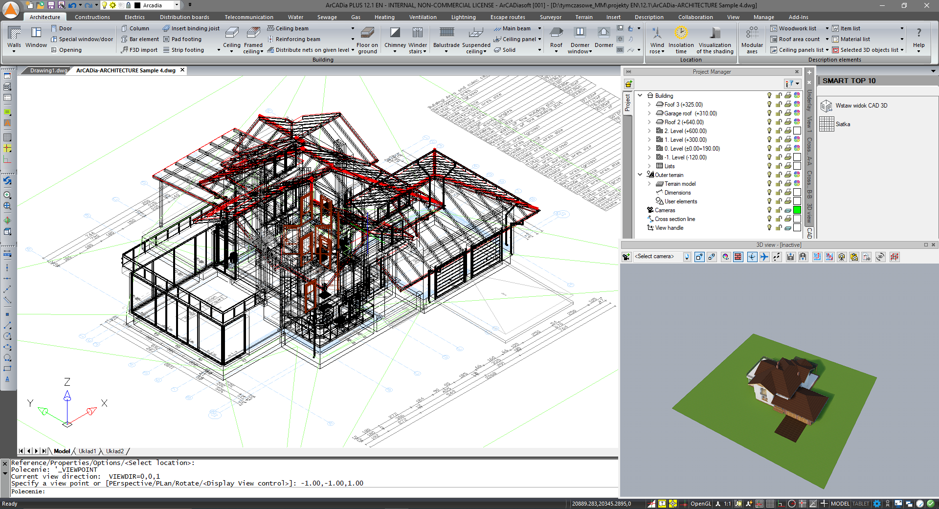
After switching to it, the drawing the building is shown in the isometric view. And there is no disabled terrain in the Project Manager window. Remember that each view has a separate visibility tree and element blocking, which you have in the project. Disabling an element in one view does not disable it in others. If you delete it then yes, because you have one model and several views. And in each view, you can turn individual elements on and off.
There is no 3D CAD view in projects you had started in the previous version. It is automatically introduced in new projects. Thanks to this, in the initial stages of drawing, you do not need to have an additional window from the 3D View turned on. It will come in handy in the later stages when adding textures and introducing furniture. CAD 3D is a linear view and in the drawing space it maps each element that is introduced in the view.
Remember, that you are still drawing in the View, but you can see the 3D elements being entered.
The CAD 3D view switches the drawing space to an isometric view by default, View 1 to a top view. The vertical toolbar on the left side of the screen includes options for navigating the workspace:


If, in any of the previous projects made in ArCADia, you want to introduce a new view, select it from the Insert or System ribbon (depending on the selected ribbon layout). Insert 3D CAD view .
Indicate the projection view so that it coincides with the View, that is preferably on the view handle.
Creating this view may take a while, the larger the project, the longer it will take. The amount of space occupied in the Windows directory will also change, the project will be several times larger.
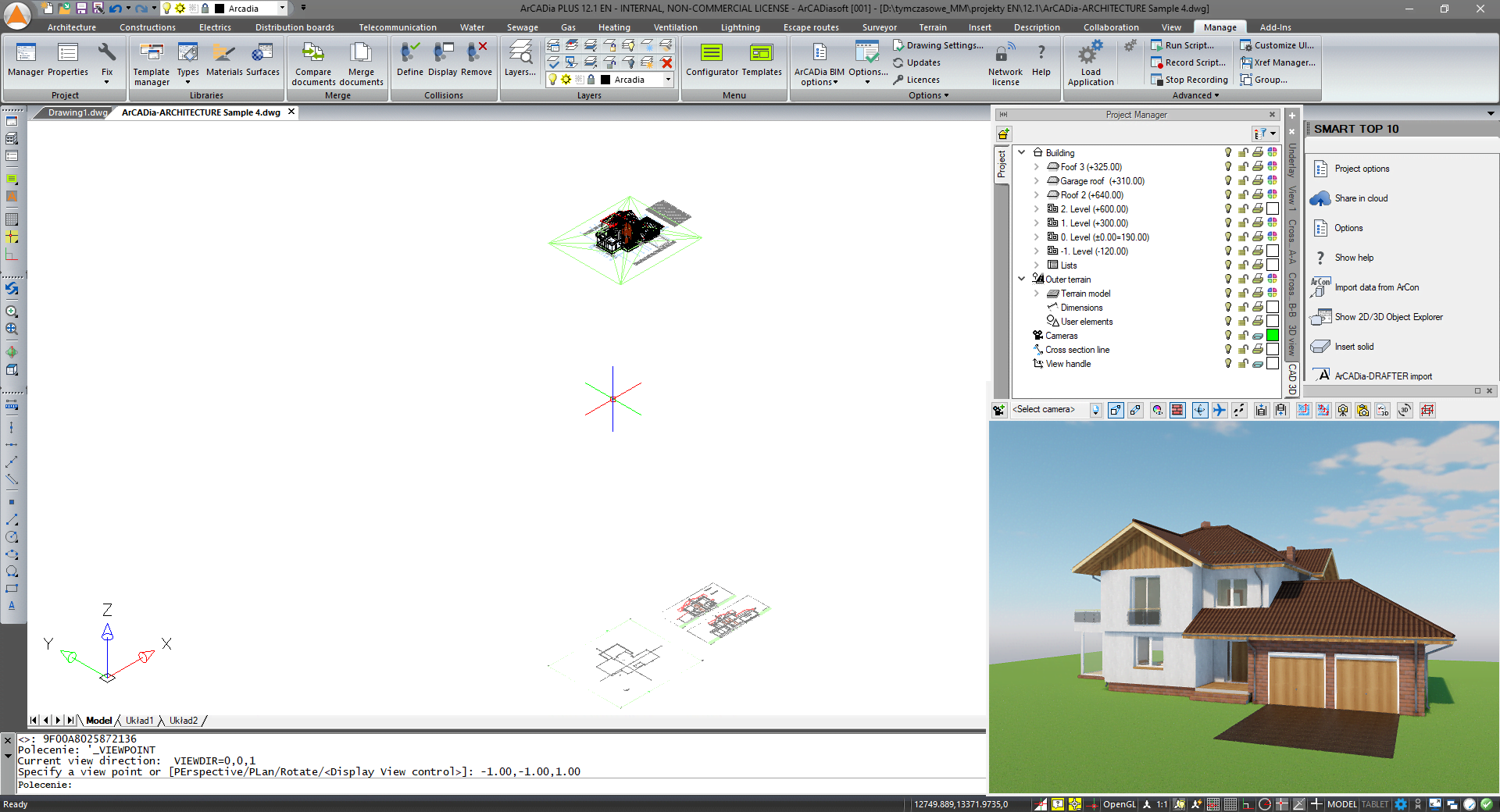
If during your work you will be inconvenienced by the automatic switching of viewports, i.e. the drawing from the top view to isometry, then in the Options window under the CAD 3D view button you can change this behaviour of the program.
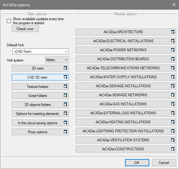
Adjust camera settings after activating the view - this option automatically sets the isometric view of the project after clicking on the CAD 3D tab. Isometry covers the entire project.
Sets the view after deactivating the view - this option shows the project in the top view after switching from CAD 3D to another view, whether it will be the View, Cross-section, Axonometry or a 3D view. The view will show the entire project again.
Therefore, if you want to define the camera setting yourself when switching between the Project Manager tabs, uncheck both options and use the icons 

Copyright © 2021 ArCADiasoft
HOME | PRODUCTS | COMPANY | CONTACT | FOR RESELLERS


