ArCADia-BIM: Construction Lines
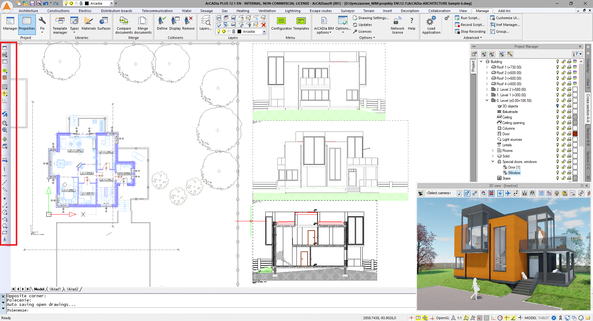
When you start the program for the first time, on the left side of the screen there are toolbars with the following icons: Show and hide the Project Manager window,
3D view, Grid and Entity Snap points. Additionally, options for refreshing the drawing, zooming in and out and auxiliary options. If the user does not turn off these toolbars, they will be present in the next program run.
All options from the left bar are also on the ribbons at the top of the screen, but in order not to look for them for a long time, they have been brought to the front.
The third toolbar is a little different from the above mentioned ones as it is an auxiliary toolbar. It starts with the distance and area icons, and below, are elements to help you draw a building or installation. The premise of these options is that they will be turned off before printing because they only have design assistance. Therefore, with their use, they are automatically entered into the Auxiliary subgroup in the User elements group on a given level or outdoor area.
The Measurement and Area and perimeter options are information about the measured elements. They are displayed only temporarily, from entering them until exiting the options. They will not stay in the drawing, but we can measure several elements by indicating the first and second measurement points. All results will disappear as soon as you press the right mouse button and ESC or Enter on the keyboard. The Area option shows the successive lengths of the selected polygon and the measurement size in the centre. After pressing the right mouse button, the ESC or Enter values are no longer displayed.
The Measurement options are the straight lines that guide you through the entire screen. You can choose straight vertical or horizontal or at an angle. The last one can be entered by specifying an angle value or selecting an angle. If you know the angle for the straight line, then after clicking on the At angle icon, you enter the value of the angle, e.g. 45, and confirm with Enter. Remember that to enter the value you do not have to click anywhere, just type 45 and confirm with the right mouse button or Enter from the keyboard. If we want to indicate an angle, we click two points on an element already existing in the drawing, so as to indicate its angle, then we get an faded line, which we will enter with the next click.
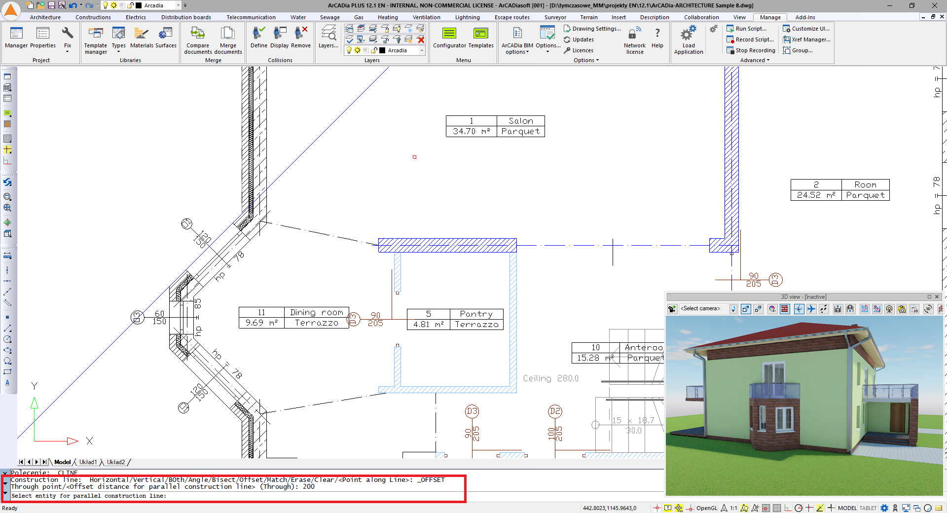
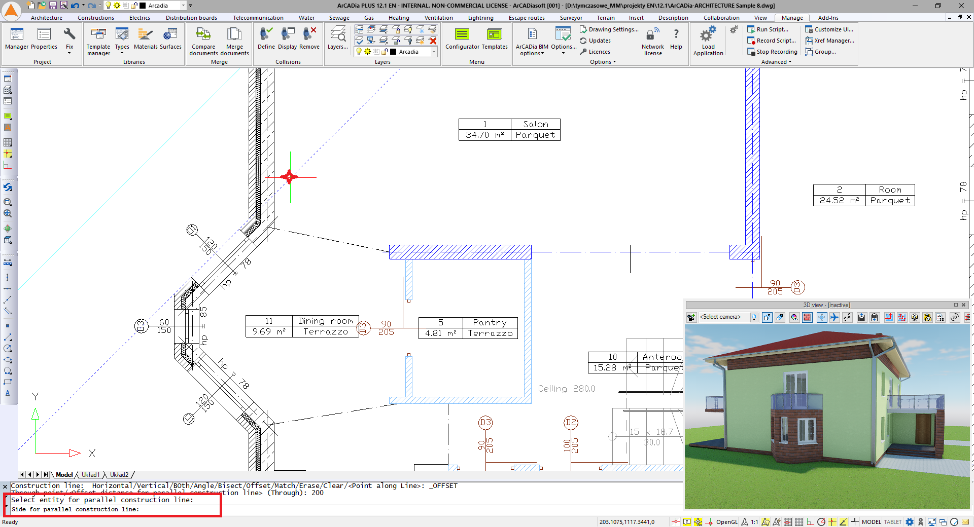
The parallel line can be entered anywhere or at a given distance from another drawing element. Here it is important that only the CAD elements, i.e. lines, polylines and lines will be the reference for this line. Walls, electrical wiring, and pipes are not. You need to draw a straight line on these elements first, and a parallel one in the next step.
After selecting the Parallel line option, you should give a value and confirm the input by pressing Enter.
Then pick an infinite line or line as a reference and indicate the side of the entered distance.
The remaining auxiliary options, when entering, either you indicate successive points or vertices, or after selecting the first one, enter the coordinates accordingly.
Copyright © 2021 ArCADiasoft
HOME | PRODUCTS | COMPANY | CONTACT | FOR RESELLERS


