ArCADia BIM: How to Change a Flat CAD Drawing to a 3D Model
If we have changed the CAD drawing tool to a more advanced one, e.g. ArCADia with system objects, then if you want to introduce old projects into the BIM model, you have to redraw them. Depending on how the drawing was created, the same procedure should take place when creating a model from the project.
The easiest way is to check the thickness of the wall and trace it using anchor points, showing the beginning and end of the wall (the wall should cover the full length, windows and doors should be inserted into it later).
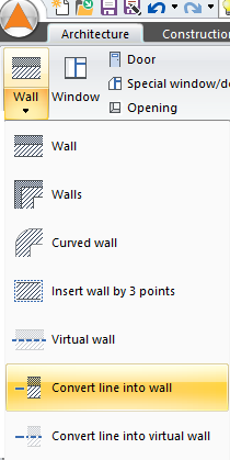
In the ArCADia-ARCHITECTURE module, there is the Convert line into wall option, which allows you to indicate a line or polyline and enter walls much faster than drawing the project contour. However, if the walls are drawn with lines, as in the section marked below, then you need to transform the line, however you do not introduce the entire wall, but only a section from the door and to the door.

An opening is formed between those sections in which the door cannot be inserted, as doors are mounted only into the wall. Do not insert another wall section in this opening, because then the door of the size given in the project may not fit there anymore. In this case, it will be faster to insert a wall by clicking on its beginning by the wall on the left and at the end by the wall on the right.
Some of the walls, the outer ones, are drawn in a slightly different way. The windows are inserted on the inside edge and the outside contour is a continuous line. In this case, we can quickly click the walls, giving the main contour.
To do this, start by measuring the thickness of the external wall, then select the Convert line into wall option from the Architecture ribbon. Select the line which is to be a wall, and when its outline appears, enter the properties (from the editing window), define the wall thickness and confirm.
If it happens, as shown in the screenshot above, that the wall does not coincide with the drawing, then you have to change the input edge, i.e. indicate a different wall input line in the editing window. Click anywhere in the drawing, thus introducing a wall.
When you mark another line, you just need to click on it and next to it, because the settings are saved. You do the same with the subsequent external walls. The interior walls and the right exterior wall should be drawn rather than transformed because the entire wall must be drawn.
Another way to convert a line to a wall would be to use a polyline. If the wall axis or one of the edges of the outer contour were a polyline, the building model would be created faster. In the example above, the axes of the wall were drawn with one element (lines can be joined into a polyline).
Thanks to this, after selecting the Convert line into wall option, selecting a polyline and selecting an appropriate entry line, the walls will be inserted simultaneously along the entire length of the polyline.
Copyright © 2021 ArCADiasoft
HOME | PRODUCTS | COMPANY | CONTACT | FOR RESELLERS


