


Collisions and cross-sections
Designing in a 3D model greatly facilitates cross-industry coordination and solving any collisions occurring in buildings.
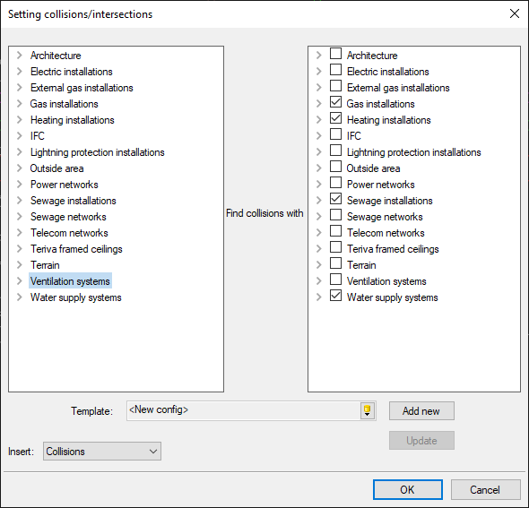
In order to find possible collisions (or installation intersections that need attention), choose the Define option (from the Manage or System ribbon depending on the chosen template) and define what elements of the collisions you are looking for - you can choose e.g., collisions of the ventilation system with the entire model, but also only with the sewage and heating installations.
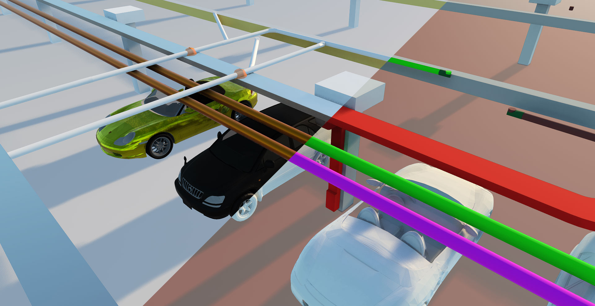
If elements collide, the program marks them in the drawing (as an orange circle with an assigned number) and in the 3D view (as an orange ball).
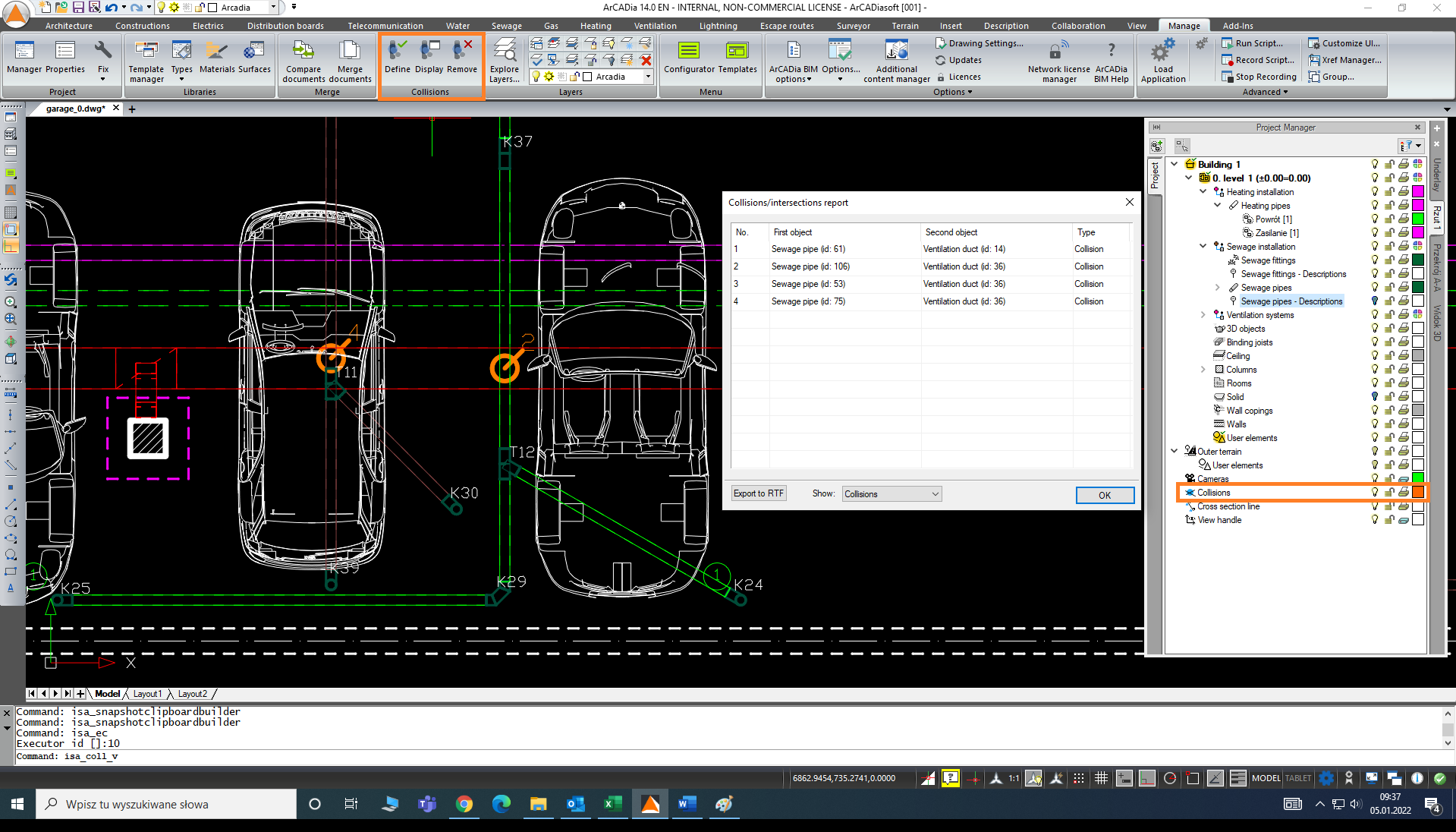
Additionally, you can view all the collisions by calling the Display command from the Collisions logical group. Such a list can be exported from the program to an external text file with the RTF extension. In the Project Manager, Collisions appear as a separate element, the visibility of which can be freely turned on or off. If we want to completely remove them from the drawing, select the Delete command from the same group of commands.
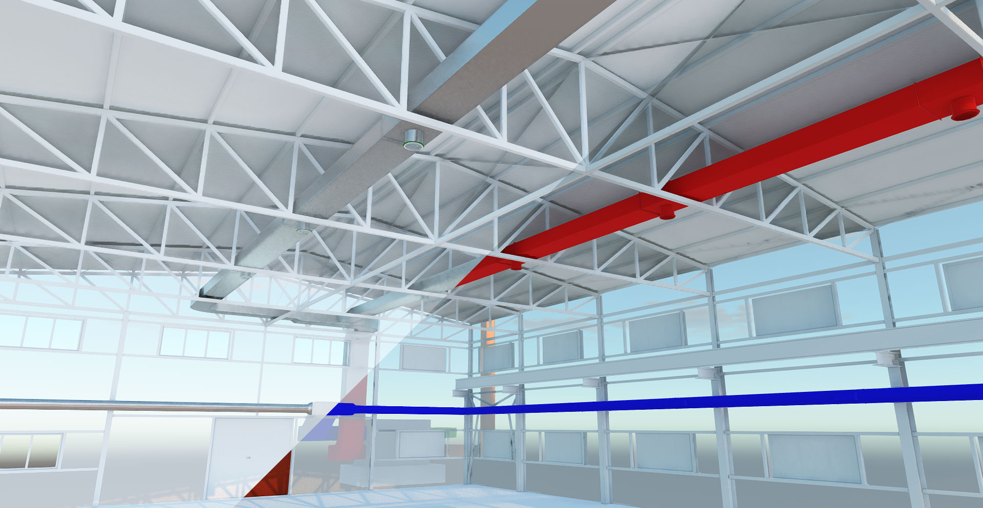
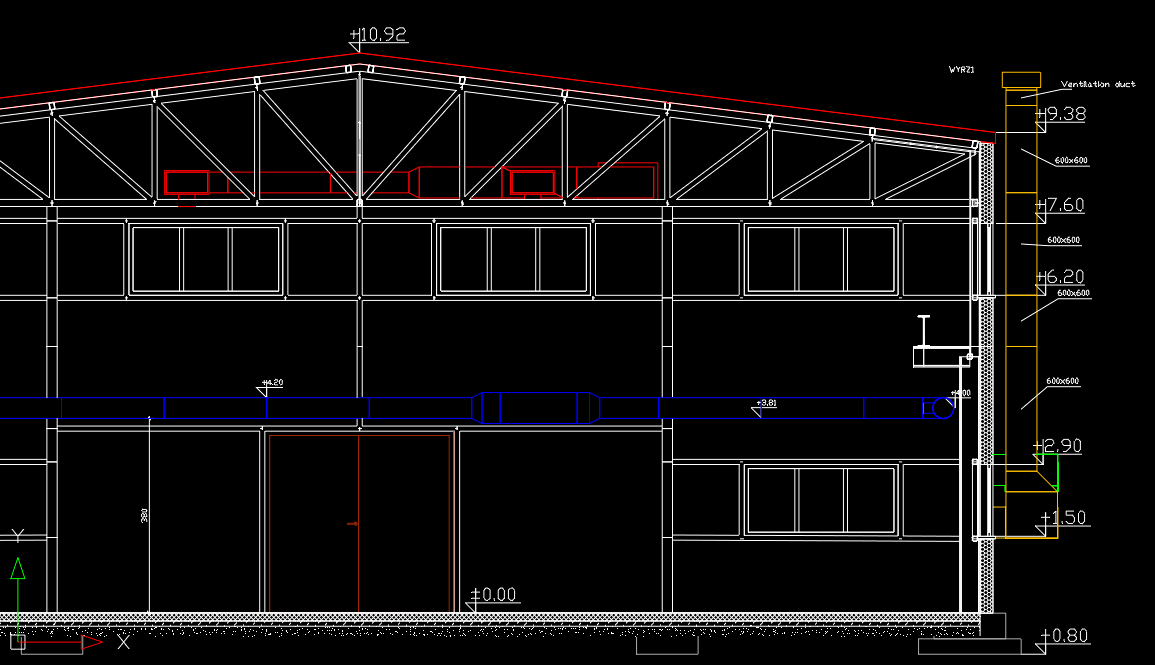
Apart from the current 3D view, thanks to ArCADia BIM, the designer has the option of making a cross-section anywhere through the building model. In addition to architecture, all installations that have already been designed will be visible in the cross-section drawing.
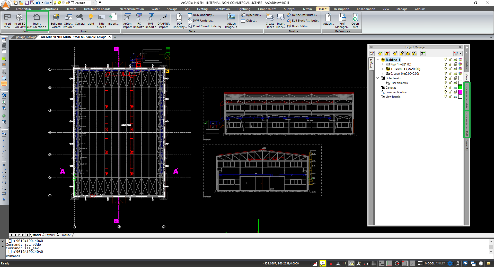
To insert a cross-section, select Insert cross-section from the Insert ribbon and specify the start and end points of the cross-section and the view direction on the view. In the next step, a View handle will be attached to the cursor, which can be placed anywhere on the drawing.
Another tab will appear in the Project Manager – Section A-A.
Inserting additional cross-sections is very useful when designing more complex installations. In technological facilities, where ventilation ducts often must fit between the trusses and technological equipment, so that they fulfill their function in the best possible way and at the same time interfere with the plant's operation as little as possible, additional views become necessary. A proficient designer can adjust the installation based on views and a few cross-sections, but when this drawing information is not enough, the BIM model becomes indispensable.
After dimensioning and entering information about the designed ventilation elements, such a drawing along with the view, can be passed on directly to the contractor - it will certainly facilitate the correct installation, without needing to ask the designer additional questions.
Copyright © 2026 ArCADiasoft
HOME | PRODUCTS | COMPANY | CONTACT | FOR RESELLERS