INTERsoft-IntelliCAD - new version
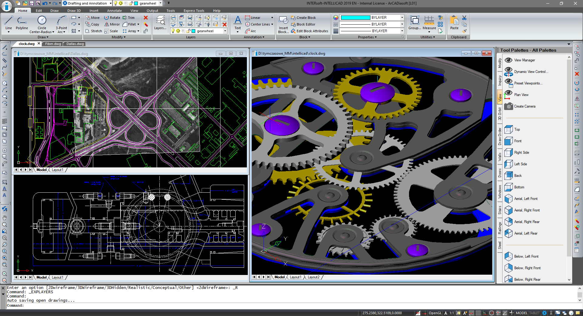
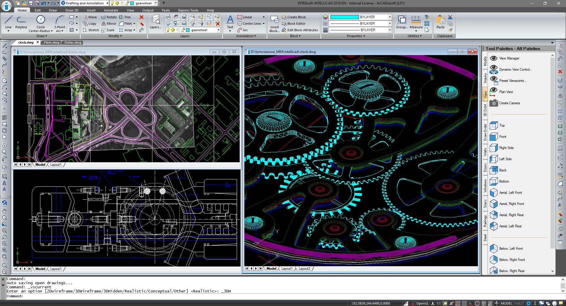
INTERsoft-INTELLICAD is a CAD program designed for creating 2D and 3D documentation. The program interface is based on ribbons, the command area and the black graphic screen. But of course, as in every CAD, there are many program personalization options here. We define which ribbons are visible, which options are displayed and which are not. Background colour, ribbon theme, minor and major grid colour, even the colour of the selection area can be defined in the Options window. If you have a small monitor, the ribbons can be rolled up automatically or you can switch to the classic view, i.e. toolbars. Anyway, toolbars are also available with the ribbons turned on. In the command area, you can enter commands, aliases, and keyboard shortcuts, depending on your needs or habits. Aliases and shortcuts can be imported from other programs, you can define your own or modify existing ones, all of which can be done in the Customize User Interface window.
Drawing takes place in the three-dimensional space of one or several views, depending on your habits. We enter values and coordinates in the command area, although we do not click on it, the program knows where to enter the value or data. We enter the coordinates as in other CADs: absolute (x,y,z), relative (@x,y,z) or polar relative (@length <angle). We can use the notification window by selecting the appropriate commands, e.g. Length or angle. When drawing, the grid, ortho option, entity snaps, tracking and entity snap tracking are helpful. Data is divided into layers and we manage them in the INTERsoft-INTELLICAD Explorer window. We draw mainly using simple elements such as line, polyline, multiline, circle, rectangle etc. (attributes can be assigned to each element) or planes placed in three-dimensional space. Planes or three-dimensional element grids can be mapped, i.e. material or texture can be added, and then we can define the background, set lighting and do the visualization. The three-dimensional model can be exported from the program as an STL file (for a 3D printer).
Other formats available to export are: DWF, DWT and DXF. PDF files can be obtained by exporting or printing to a file. The print sheets are defined on paper tabs and all elements placed on them are not visible in the design model.
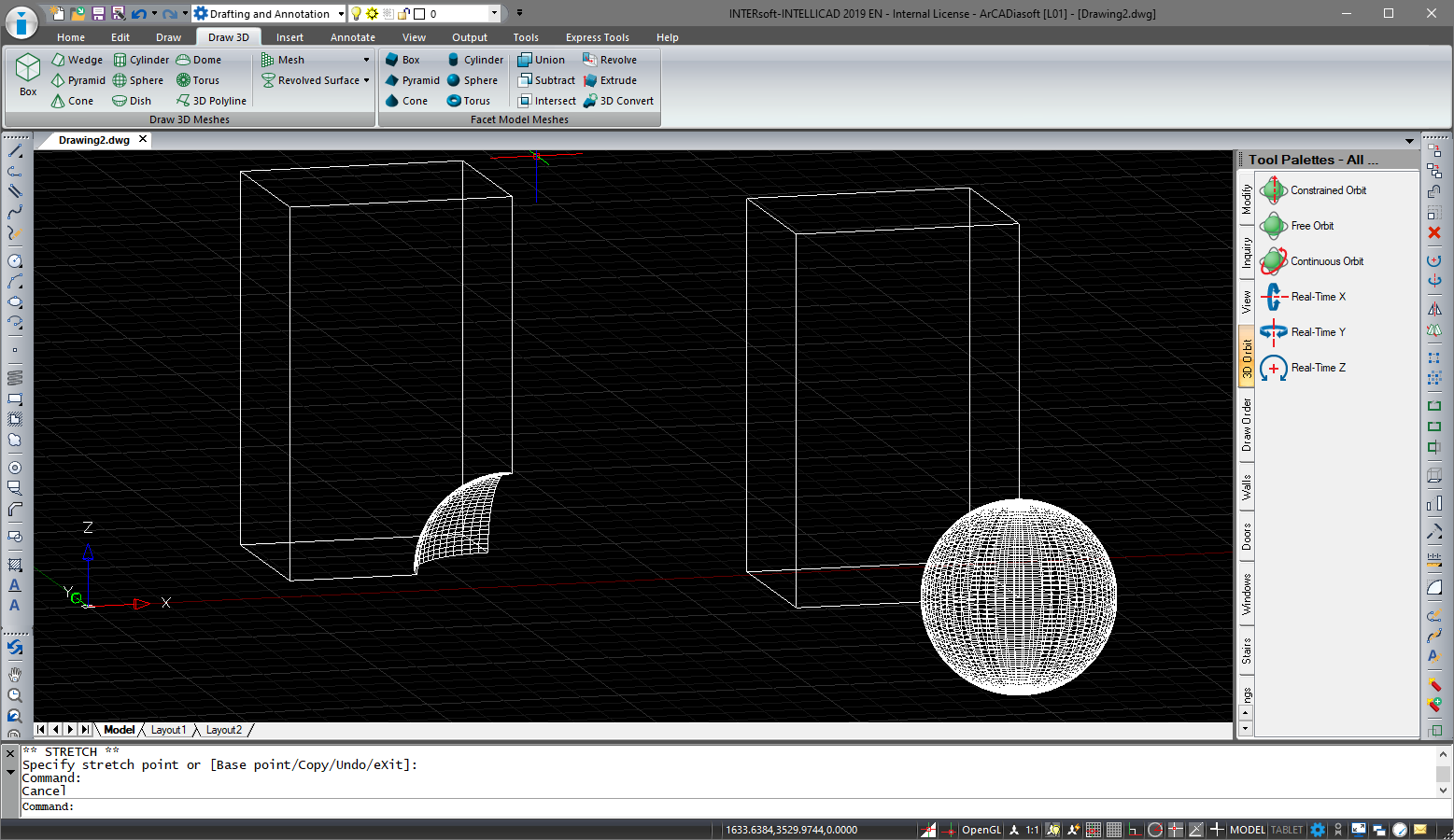
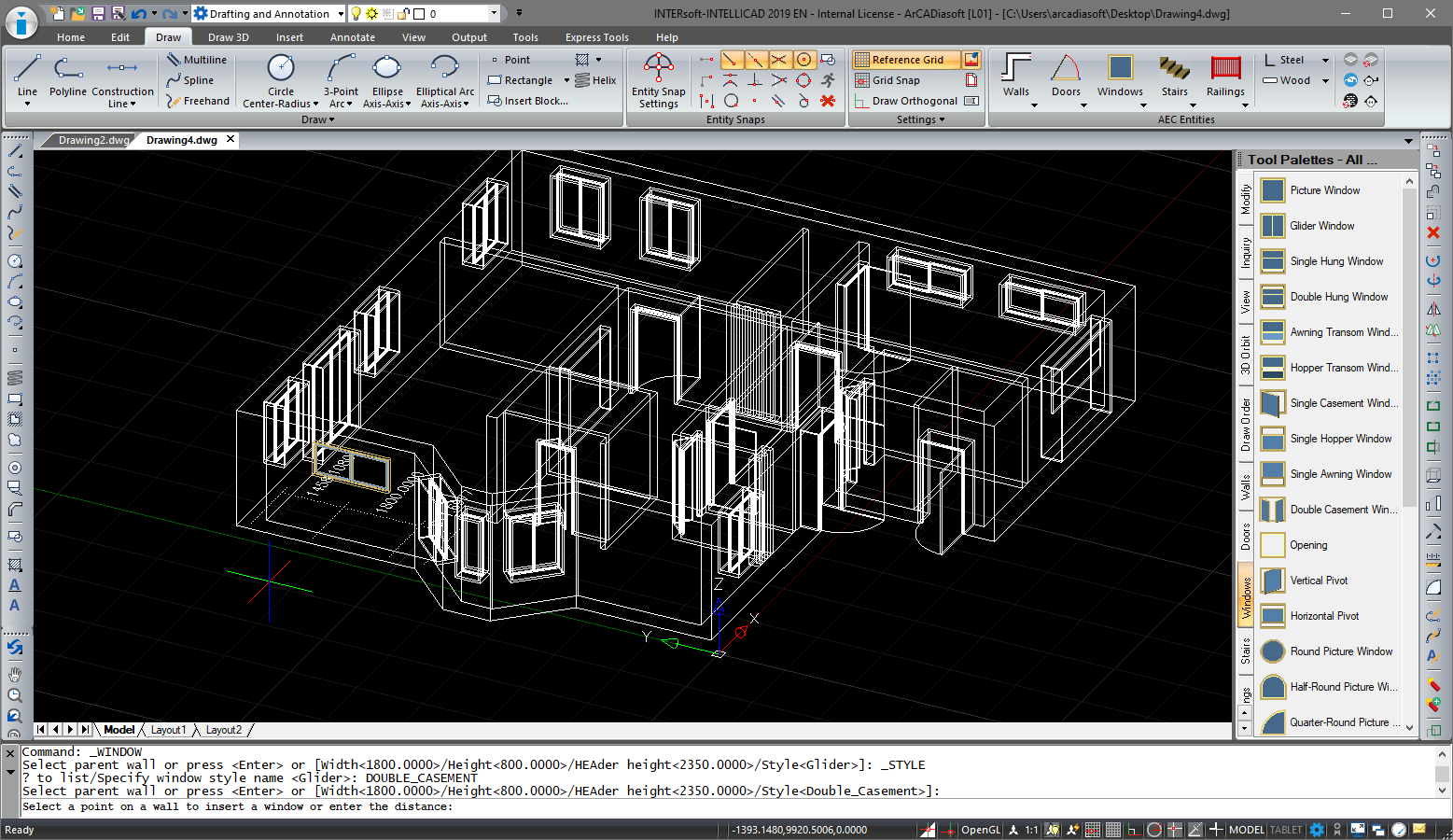
The new version of the INTERsoft-INTELLICAD program opens and saves files in the DWG 2018 format. In addition to a format change, the application has the ability to load files in the following formats: RVT, RFA (Revit); IFC (BIM programs) and RCP, RCS (point cloud). All these formats introduce underlays to the project, on which further drawing elements can be embedded. The 3D design has also been expanded by new Facet Modeler objects as well as the introduction of walls, windows, doors and ceilings. Facet Modeler objects contain basic 3D objects such as box, pyramid, cone, cylinder, sphere and torus. Additionally, these elements can be modified with each other, e.g. using options: union, subtract, intersect. The walls which are drawn in the INTERsoft-INTELLICAD 2019 program are 3D elements in which windows, doors and openings can be inserted. No layers or materials are assigned to them, but level projections can be created.
The construction lines are very useful elements when drawing. This new option lets you enter a grid of axes, guide lines or infinite elements that help you draw.
The construction lines available in INTERsoft-INTELLICAD:
• horizontal,
• vertical,
• angled,
• bisect angle,
• bisect entity,
• on entity,
• offset.
In addition, if for example we have an already imported drawing, we can automatically outline it by using lines that are horizontal, vertical or automatically both.
When designing, you can also use the move/copy/rotate options, which have now been combined into one option so during drawing you can switch and change the modification options.
A similar facilitation is the addition of the Tool Palettes, which can be placed on the left or right side of the program window. By default, several palettes have been created with options for modification, moving around the project (view and orbit options), queries, and display order. They are located on the right side of the program window.
When describing drawings, the options for dividing text into columns, entering text in an arc and text in contours, i.e. surrounded by a rectangle or circle is very useful.
Copyright © 2021 ArCADiasoft
HOME | PRODUCTS | COMPANY | CONTACT | FOR RESELLERS


