


Creating your own project in ArCADia BIM on the IFC model
If we would like to draw our own elements into the project – e.g. installations, we must create a building in the project manager with floors on the appropriate elevations. To determine the actual ordinates, designed by the architect, it is best to make a cross-section and read the ordinates based on it.
The way to do this is described in detail in the article:
https://arcadiabimsystem.com/arcadia-ifc-rvt-working-with-an-imported-ifc-file
In the project manager, we go on the left to the Project tab, and on the right to the View and insert a new Building.

Next, we determine the elevations of the levels according to the data in the project.
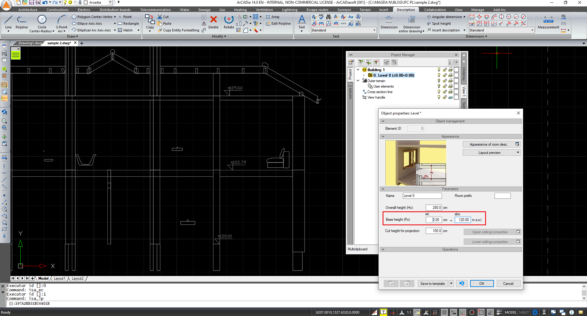
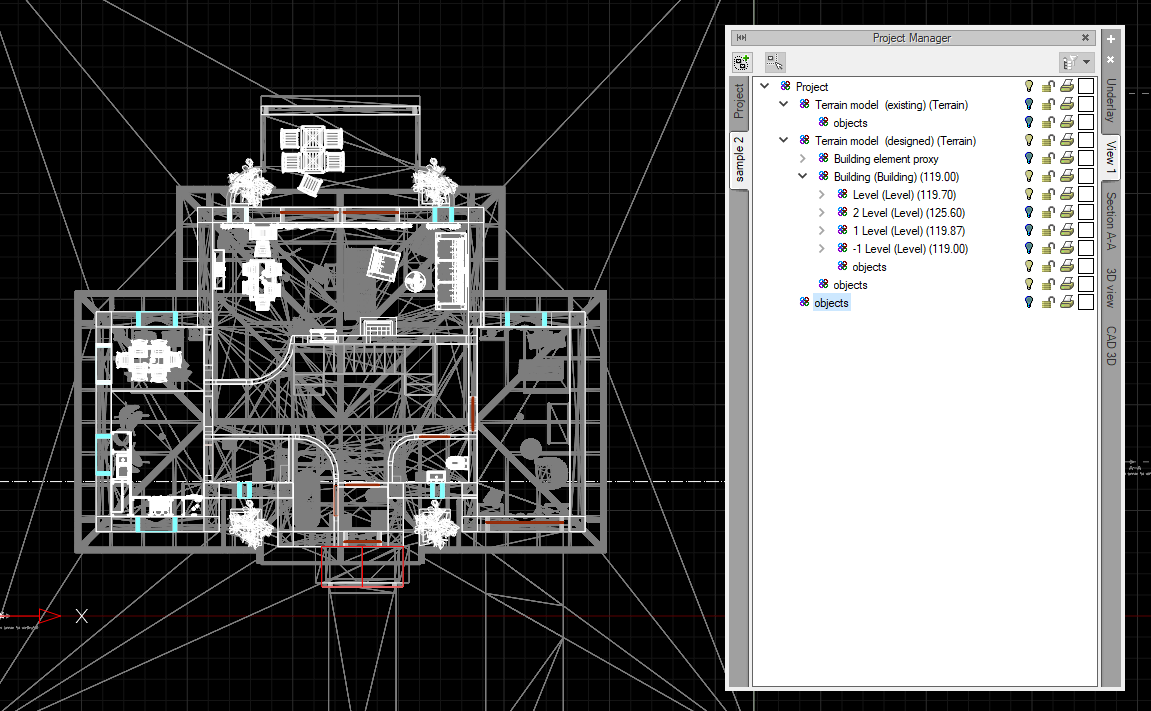
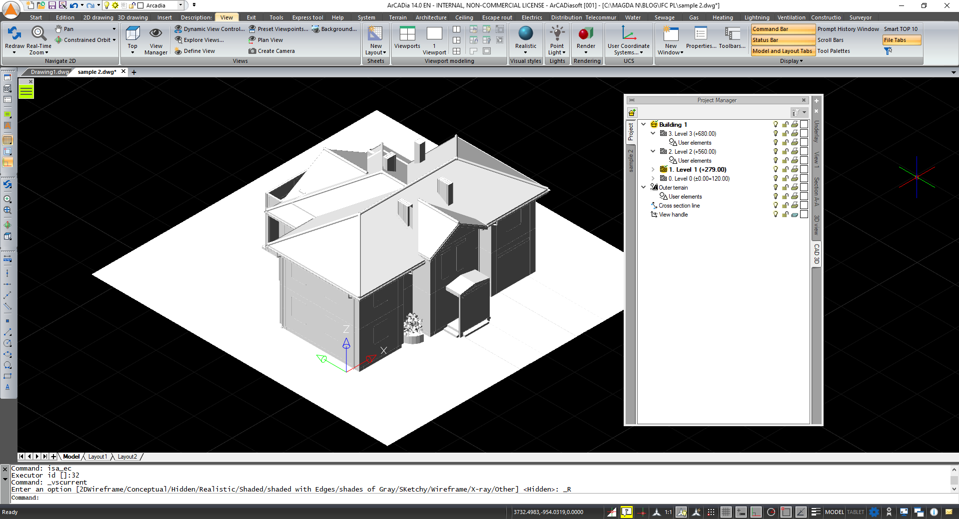
Below is a view of the project manager with defined levels.

In a file prepared this way, we can start the design work by inserting elements on the appropriate levels. If we want to get a view only of the ground floor of the building, we disable on the IFC model tab, the visibility of the remaining floors (using the "light bulb" symbol).
If your project is still not clear enough, check if there is a 3D CAD tab in the project manager. Since the arCADia 12 version, a new 3D CAD view is automatically introduced - by default, a three-dimensional, mesh design model placed in the drawing area.
More information about the 3D CAD view can be found on the blog:
https://arcadiabimsystem.com/a-new-view-in-arcadia-12
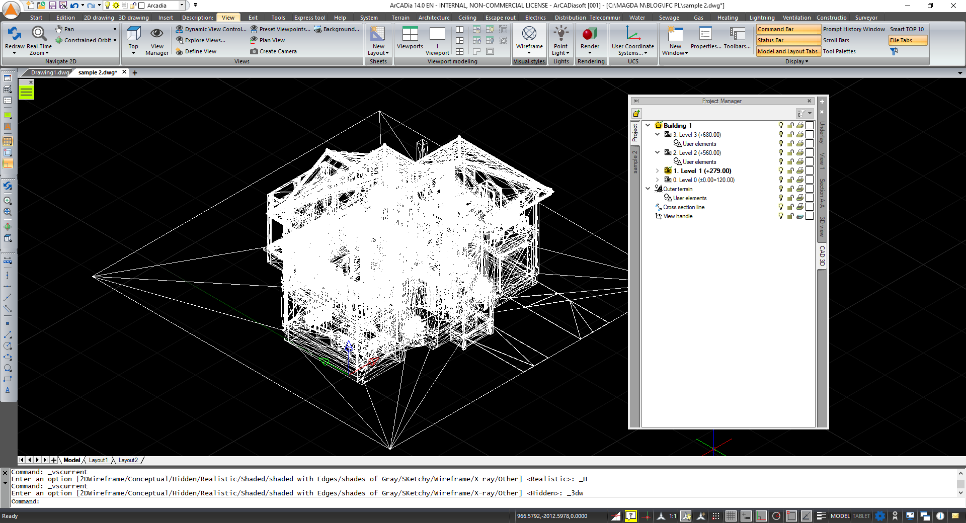
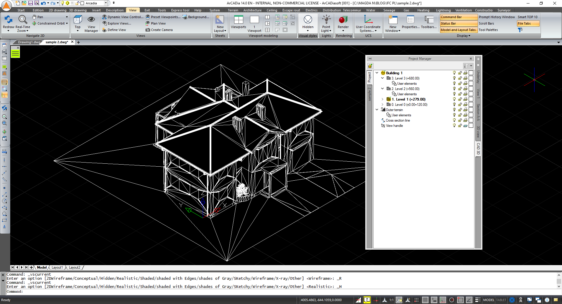
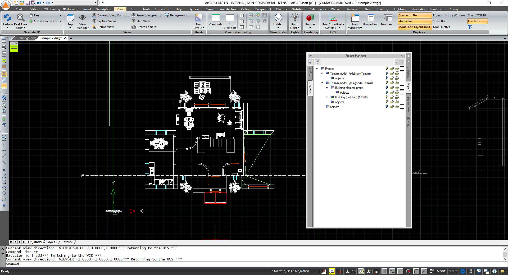
After loading the IFC model, it was mirrored as a "normal" three-dimensional model in the file. After switching to the 3D CAD tab, depending on the visual style settings, we will see the building model (visual style 2D/3D mesh hidden/Realistic):
Staying on the CAD 3D tab, we disable the visibility of the entire building (on the left Project tab) and the visibility of the IFC model (on the left tab of the ifc model) or completely remove the 3D CAD tab from the project - you can insert this view again at any time. As a result, we get the view of the desired level resulting only from the IFC model.
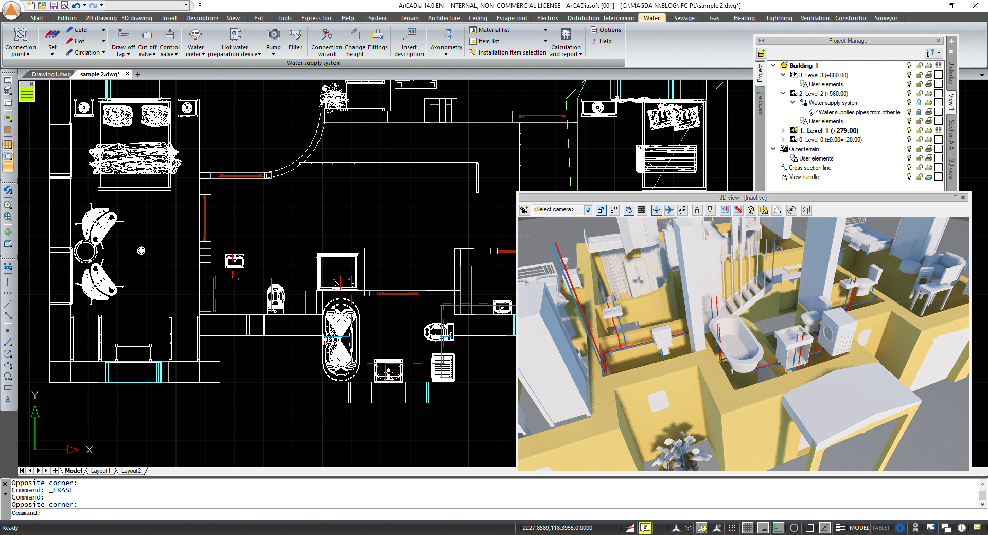
On a file prepared in this way, we can start designing the installation in the standard way. The figure below shows the design of a plumbing system, designed on an IFC model.
Copyright © 2021 ArCADiasoft
ГОЛОВНА | ПРОДУКЦІЯ | ПРО НАС | КОНТАКТИ | ДЛЯ ПРЕДСТАВНИКІВ